(Edit: My entry on the Gallery of Fluid Motion using this technique is online!)
(Edit 2, 2023: I published this circuit on my Github page, if you want to build this. The updated circuit is a very simplified version. It works pretty well, though, once you understand the limitations. See here: https://github.com/3dfernando/Shadowgraph_LED_Driver/blob/main/README.md)
For the ones not introduced to the art of Schlieren photography, I can assure you it was incredibly eye-opening and fascinating to me when I learned that we can see thin air with just a few lenses (or even just one mirror as Josh The Engineer demonstrated here on a hobby setup).
For the initiated in the technique, its uses are obvious in the art and engineering of bleeding-edge aerodynamic technology. Supersonic flows are the favorites here, because the presence of shock waves that make for beautiful crisp images and help us understand and describe many kinds of fluid dynamics phenomena.

What I’m going to describe in this article is a very simple circuit published by Christian Willert here but that most likely is paywalled and might have too much formalism for someone who is just looking for some answers. Since the circuit and the electrical engineering is pretty basic, I felt I (with my hobby-level electronics knowledge) could give it a go and I think you also should. I am also publishing my EasyEDA project if you want to make your boards (Yes, EasyEDA).
But first, let’s address the elephant in the room: Why should you care? Well, if you ever tinkered with a Schlieren/shadowgraph apparatus – for scientific, engineering or artistic purposes -you might be interested in taking sharper pictures. Obtaining sharper pictures of moving stuff works exactly like in regular photography. They can be achieved by reducing the aperture of the lens, by reducing the exposure time or by using a flash. The latter is when a pulsed light source really shines (pun intended!). The great part here is that the first two options involve reducing the amount of light – whereas the last option doesn’t (necessarily).
The not-so-great part is that camera sensors are “integrators”. This means they measure the amount of photons that happened to be absorbed given an amount of time. Therefore, what really matters is the total amount of photons you sent to the camera. Of course, if you sent an insanely large amount of photons in a very short instant, you would risk burning the camera sensor – but if you’re using an LED (as we are going to here), your LED will be long gone before that happens.
So the secret for high speed photography is to have insanely large amounts of light dispensed at once. That would guarantee everything will be as sharp as your optics allow. Since we don’t live in the world of mathematical idealizations, we cannot deliver anything “instantly”, and therefore we have to live with some finite amount of time. Brief enough is relative and depends on what you want to observe. For example, if you’re taking a selfie in a party, probably tens of milliseconds is brief enough to get sharp images. For taking a picture of a tennis player doing a high speed serve, you’re probably fine with tens or hundreds of microseconds. The technical challenges begin to appear when you’re taking pictures of really fast stuff (like supersonic planes) or at larger magnifications. The picture of the jet above is challenging in both ways: its magnification level is 0.7x (meaning the physical object is as projected in the sensor at 0.7x scale) and its speed is roughly 500 meters per second. In other words, the movement of the object (the Schlieren object) is happening at roughly 63.6 million px/second, which requires a really fast shutter to have any hopes to “freeze the flow”. If you’re fond to making simple multiplications in your calculator, the equation is very simple:
Where 


I know, I know. These are very specialized applications. But who knows which kinds of high speed photography is happening right now in someone’s garage, right? The point is – getting a light source that is fast enough is very challenging. Some options, such as laser-pulsed plasma light sources, can get really expensive even if you make them yourself. But LEDs are a very well-established, reliable technology that has an incredibly fast rise time. And they can get very bright, too (well… kinda).
So what Willert and his coauthors did was very simple: Let’s overdrive a bright LED with 20 times its design current and hope they don’t explode. Spoiler alert: Some LEDs didn’t survive this intellectual journey. But they mapped the safe operational regions for overdriven LEDs of many different manufacturers. To name a few: Luminus Phlatlight CBT-120, Luminus Phlatlight CBT-140, Phillips LXHL-PM02, among others. These are raw LEDs, no driver included, rated for ~3.6-4V, and are incredibly expensive for an LED. The price ranges from $100 to $150, and they are usually employed in automotive applications. The powerful flash is, however, blinding. And if they do burn out, it can be harmful for the hobbyist’s pockets.
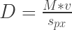
The driver circuit (which is available here) is very simple: An IRF3805 N-channel power MOSFET just connects the LED to a 24V power supply. Remembering the LED is rated for 4V – so it’s going to get a tiny bit brighter (sarcasm). Jokes apart, the LED (CBT-140) is rated for 28A continuous with very efficient heatsinking, which means we will definitely be overdriven. By how much we can measure with R2. Hooking a scope between Q1 and R2 is not harmful to the scope and allows to measure the current going through the LED (unless the currents exceed ~600A, then the voltage spike when the MOSFET turns off might be on the few tens of volts). We don’t want to operate at these currents anyways, because the LED will end up as in the figure below. There’s a trim pot (R3) that controls the MOSFET gate voltage, make sure pin 2 of U1 is giving a low voltage when tuning.

What is really happening is that C1 and C2 (C2 is optional) are being charged by the 24V power supply when the MOSFET is off. Then they discharge at the LED when the MOSFET is activated. No power supply will be able to push 200A continuously through an LED, so if the transistor turns on for too long, the power supply voltage will drop and the power supply will reset. Actually, this is one of the ways to tell if you melted the MOSFET (which happened to me once). The MOSFET needs to turn on in nanoseconds, which will require a decent amount of current (like 4-5 amps) just to charge the gate up. This means we need a driver IC – which in this case I’m using a UCC27424. Make sure to have as little resistance between the driver and the gate to minimize the time constant. The 1.5 Ohms is very close to giving 4A to the MOSFET. Since the gate capacitance is around 8nF, the MOSFET gate rise time is somewhat slow (12 ns).
Speaking about time constants, during the design I realized the time constants of the capacitor that discharges into the LED and the parasitic inductances in the path between the components will dictate the rise time of the circuit, at least for the most part. In my circuit, the time constant was measured to be 100ns, directly with a photodiode. This means we can do >1MHz photography, which is pretty amazing! Unfortunately the cameras that are capable of 1 million frames per second aren’t really accessible to mortals (except when said mortals work in a laboratory that happens to have them!).
Well, the LED driver circuit is still in development – which means I’ll keep this post updated every now and then. But for now, it’s working well enough. The BOM cost is not too intimidating (~$60 at Digikey without the LED. Add the LED and we should be at ~$200), so a hobbyist can really justify this investment if it means an equivalent amount of hours of fun! Furthermore, this circuit implements a microcontroller that monitors and displays the LED and driver’s temperature. It features an auto shut-off, which disables the MOSFET driver if the temperature exceeds an operational threshold. The thermal limits are still to be evaluated, though.

For now, I did my own independent tests, and the results are very promising. Below I’m showing a test rig to evaluate the illumination rise and fall times of the LED. The photodiode is a Thorlabs (forgot the model) that has a 1ns rise time if attached to a 50 ohm load. It’s internally biased, which is nice when you want to do a quick test.

The results from the illumination standpoint are rather promising. Below a series of scope traces show that the LED lights up in a very short time and reaches a pretty much constant on state. The decay time, however, seems to be controlled by a phosphorescence mechanism that is probably because this is a white LED. Nevertheless, the pulses are remarkably brief.


The good thing about having high speed cameras is that now we’re ready to roll some experiments. By far, my favorite one is shown below. I was able to use the Schlieren setup to observe ultrasonic acoustic waves at 80kHz , produced by a micro-impinging jet (the jet is 2mm in diameter). The jet is supersonic, its velocity is estimated to be 400 m/s. Just to make sure you get what is in the video: The gray rectangle above is the nozzle. The shiny white line at the bottom is the impingement surface. The jet is impinging downwards, at the center of the image. The acoustic waves are the vertically traveling lines of bright and dark pixels. I was literally able to see sound! How cool is that?
Just as a final note. You might be discouraged to know that I am one of these mortals that happen to have access to a high-speed camera. But bear in mind, these pictures could have been taken with a regular DSLR. The only difference is that the frame sequence wouldn’t look continuous, because the DSLR frame rate is not synchronized with the phenomenon. Apart from that, everything else would be the same. You should give it a try! If you do, please let me know =)

Write more, thats all I have to say. Literally, it seems as though you relied on the video to make your point. You clearly know what youre talking about, why waste your intelligence on just posting videos to your site when you could be giving us something enlightening to read?
LikeLike