So I’ve been working on a hobby project that involves transferring power to a circuit wirelessly. The distance is quite short (<10mm), as I just need to have one part of the device spinning and the other stationary.
I decided to stick with LC resonant coupling circuits as a solution to transfer this power, as I can admit for some power loss and having low audible noise is a requirement. But while I was studying this circuit, I wanted to know what would be the best conversion efficiency attainable, and also I was interested in understanding why in the first place a resonant circuit is needed (why not just use a regular circuit like a transformer?).
To answer these questions, I was thinking of building the circuit model in a simulator (as in the picture shown below), and simply playing with the parameters should give me a good grasp on what was happening.

While it did help me understand some concepts, it still was not very clear what was the effect of the coupling coefficient (k) on the power dissipated in the load and the overall power transfer efficiency of the system. So I decided to step up a little bit and use Matlab. The simple code I wrote is in this link and you can also play with the parameters for your circuit.
Basically, I used the control systems toolbox to write the transfer function of the circuit. The transfer function I’m interested on, eta, is the power dissipated in the load ZL divided by the power generated in the source Vin. The remaining power should be dissipated in the source itself, through its own impedance ZS.
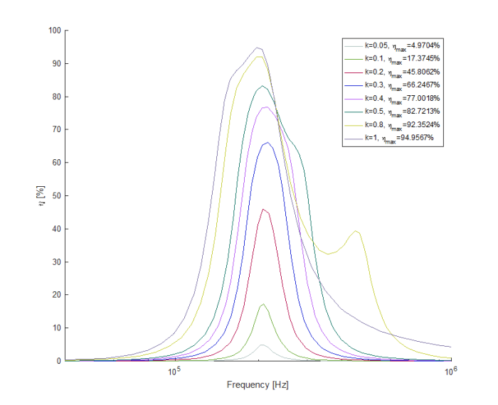
The plot of frequency response for many coupling factors (as shown below) is rather interesting: It shows there is indeed a dependence of peak power transfer efficiency as the coupling factor increases. But it shows also that you don’t need a very large coupling factor to get interesting efficiencies (for k=0.4, eta peaks at 77%, for example). This means we don’t need astonishingly good coupling (as in a transformer, for example, where k>0.98) to transfer power. I know, this conclusion has already been made by smarter researchers than me long ago, but it’s nice to arrive at it by myself anyways.
The following picture shows the same information, but complies the peak efficiencies against the coupling factor k. It shows that below a certain coupling factor (~0.4) the power transfer efficiency plummets. Unfortunately, this means that for large distances the resonant circuit is not the solution (as everyone already knows!), since the coupling factors are absurdly small for these distances.
Even so, for my simple peasant application of transferring power through a 10mm air gap that’s more than enough enlightenment in the topic.

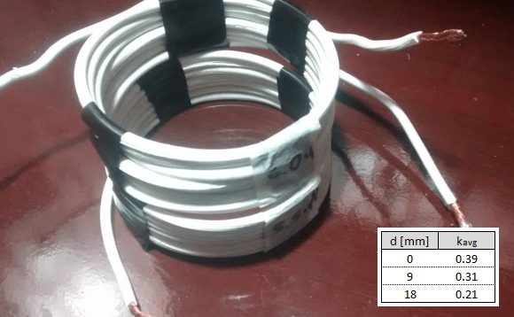
Just for the record, I measured the inductances of my homemade pair of coils (5.5µH and 6.0µH, as stated in the figure) and the coupling factor against distance (no capacitors, just the coils, using the open circuit voltage method, f=50 to 800 kHz) and the results are as shown below. According to the charts I generated, then, I should be fine, right? Well, it will depend whether I can make a MOSFET driver that will be able to attain a nice efficiency factor to multiply these maximum eta values I obtained!

One thought on “Resonant Coupling Efficiency for Wireless Power Transfer”