Maybe this is happening to you at this very moment: You build a shadowgraph, spend hours or days aligning the optics and finally get the camera installed. You put a regular camera lens, used in photography, to preserve the image quality as much as possible. You start focusing the focal ring of the lens such that it focuses on the test section where the shadowgraph object will be. But you can’t seem to get it in focus, no matter what. You spin the focal ring, frantically, back and forth. No position of the focal ring focuses the damn shadowgraph! Oh. My. God. You suddenly come to the realization. This will not work. Days of alignment to waste. Now what?!
The story above happened to me all too many times, so I decided to share my experience and solution with the world. Spoiler and TLDR: Just put a divergent lens in front of the camera!
Back to basics
So I’ll first set the scope of this discussion to a Focused Shadowgraph, which is the most typical shadowgraph encountered in aerodynamics labs. The focused shadowgraph is comprised of the following elements:
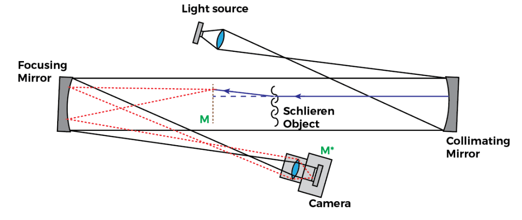
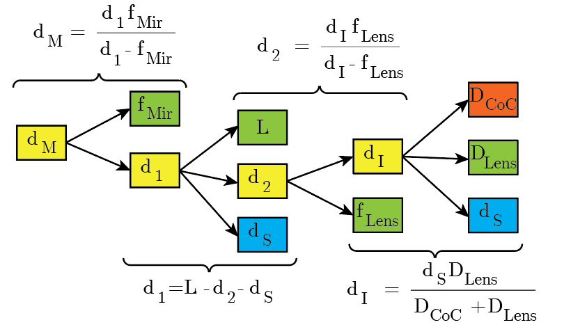
The image above represents the typical focusing shadowgraph system. It looks like a Z-type Schlieren apparatus, but is not to be confused: The Focusing Shadowgraph creates a conjugate focal plane at the camera location M*, forming a copy of the shadowgram at M in the camera sensor.
The optical setup shown uses two optical elements to focus the shadowgram plane M into the camera sensor plane M*: A focusing mirror (typically the same mirror specs as the collimating mirror); and the camera lens. The fact there are two focusing optics places a strong limitation when it comes to getting the focus at the plane M.
optical calculations
Since we’re focusing at plane M, we can consider only the optics between plane M and the camera, for our focusing calculations:
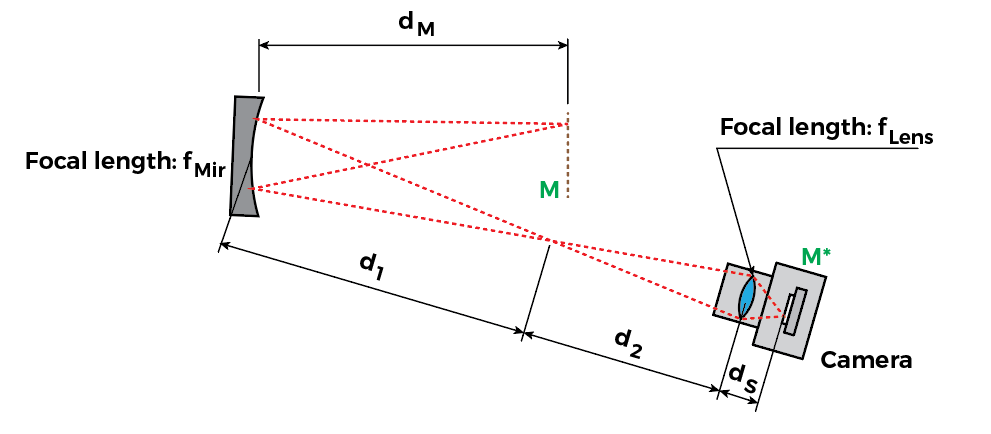
We have an intermediary conjugate plane between the mirror and the camera, whose distance can easily be found with the thin lens equation:

Consider that when we’re focusing the lens, usually 
To make the math a little easier to handle, we need to allow the camera to become out-of-focus, as we will be dealing with some singular points in this calculation. So let’s define the size of the circle of confusion. I’ll “zoom into” the camera so this becomes clearer:
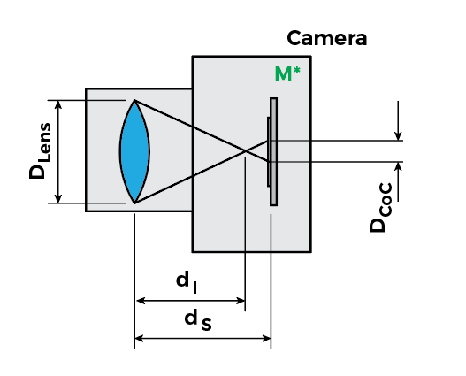
In this configuration, the camera is out-of-focus and the lens focuses at 


The image is in perfect focus when 

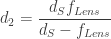
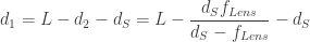
Now we can use the thin lens equation to find

Here things get a little dicy, because we have many ways of solving this problem. So let’s say we wanted to find the position of the conjugate focal plane 
The constants are shown in green, and the two variables we want to work with are shown in blue (


The focus problem
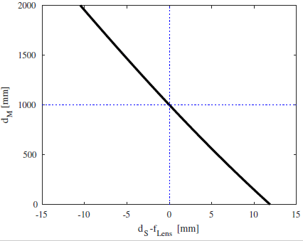
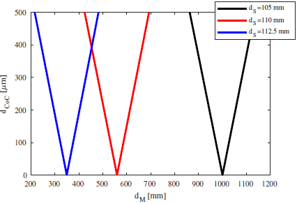
The previous plot shows us something quite remarkable: For positive 

Well, let’s look at a regular lens used in photography. For simplicity, we’ll use a lens with fixed focal length and only control over the focus ring. This lens, even though it is a compound system of lenses (usually with only two elements), can be replaced by a single “effective lens”, for the purposes of the thin lens equation calculation. If the lens is focusing at infinity, its distance from the sensor is exactly 


This places a great limitation on the “focused shadowgraph” ability to focus. The farthest it can focus from the Focusing Mirror is exactly the focusing mirror’s focal length,
For
Well, when focusing at infinity, 

Then we can easily find that:

But 

I like the interpretation with the circle of confusion, since it gives a sense of how the shadowgraph focusing looks like. For the same setup described, let’s look at the circle of confusion size for various lens distances:
SOLUTION #1 – FOCUS BEYOND INFINITY!
Yes, you read it right: Your lens setting focusing at infinity is limited. So you have to focus BEYOND infinity. Sounds crazy?
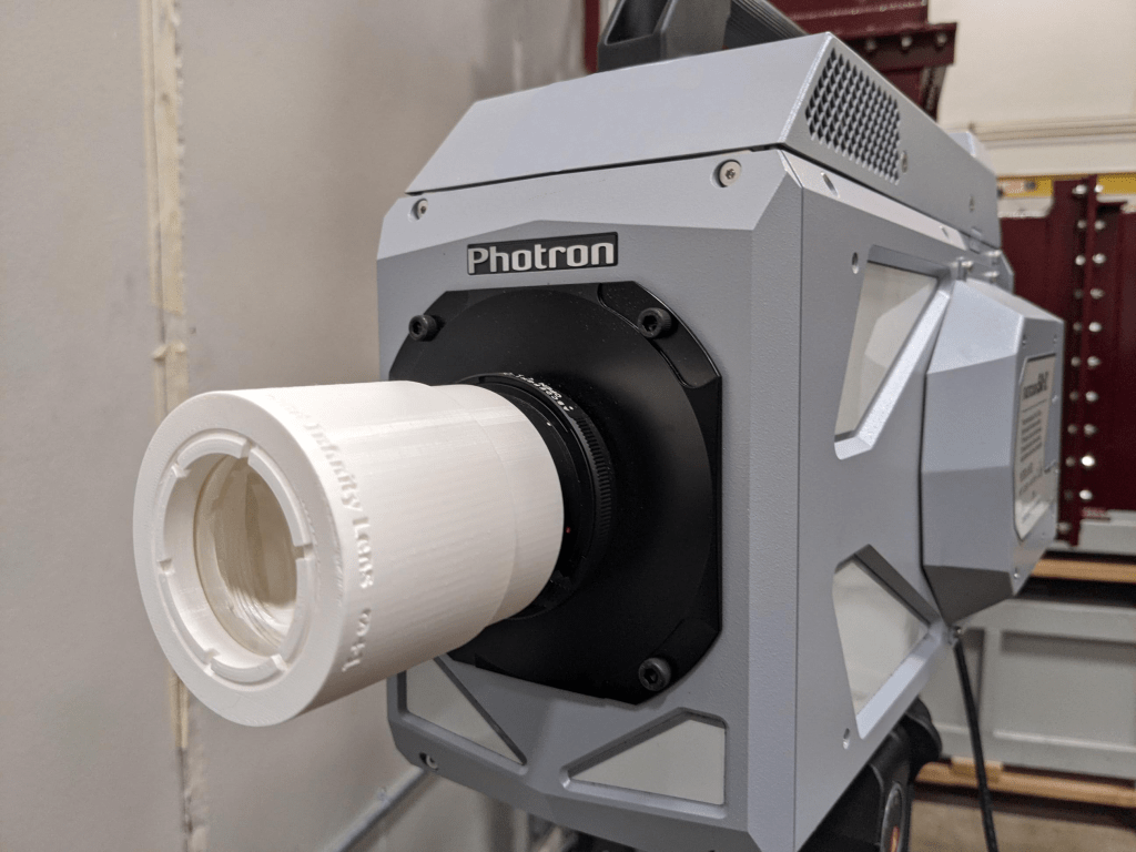
Well, I 3D printed a lens holder for a Nikon camera mount (see Thingiverse file here) that accepts a single 2″ lens. I used, in my case, a 125mm achromatic lens for this purpose. So this is a single-element lens, but now I designed such that its distance to the sensor is less than 125mm (less than its focal length). This would mean this lens would never focus in regular conditions, since it’s trying to focus beyond infinity. However, in the shadowgraph, we have the mirror as an extra optical element, which allows this lens to focus properly. Let me know if you found this idea useful, I’d love to hear your thoughts!
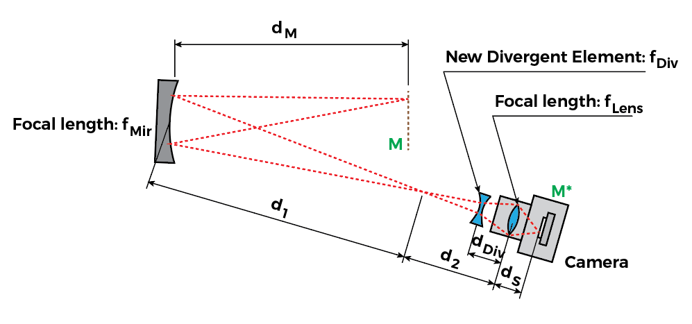
sOLUTION #2 – ADD A DIVERGING LENS
Another option (I hadn’t tried this yet): Just add a divergent lens in front of the camera lens! The divergent lens will “correct for” the focusing effect of the focusing mirror, extending the focal distance. I’ll leave out a drawing here of the setup; but I’ll leave the optical calculations to your specific setup.