As a disclaimer, I’m applying this technique in a scientific setting, but I’m sure the same exact problem arises when doing general macro photography. So, first, what is a Scheimpff…. plug?
Scheimpflug is actually the last name of Theodor Scheimpflug, who apparently described (not for the first time) a method for perspective correction in aerial photographs. This method is apparently called by many as “the Scheimpflug principle”, and is a fundamental tool in professional photography to adjust the tilt of the focal plane with respect to the camera sensor plane. It is especially critical in applications where the depth of field is very shallow, such as in macro photography.
As an experimental aerodynamicist, I like to think of myself as a professional photographer (and in many instances we are actually more well-equipped than most professional photographers in regards to technique, refinement and equipment, I reckon). One of the most obnoxious challenges that occurs time and again in wind tunnel photography is the adjustment of the Scheimpflug adapter, which is the theme of this article. God, it is a pain.
What is in focus?
First let’s start to define what is “being in focus”. It is not very straightforward because it involves a “fudge factor”, called the “circle of confusion”. The gif below, generated with the online web app “Ray Optics Simulator“, shows how this concept works. Imagine that the point source in the center of the image is the sharpest thing you can see in the field of view. It could be anything: The edge of the text written in a paper, the contrast between a leaf edge against the background in a tree, the edge of a hair, or in the case of experimental fluid dynamics, the image of a fog particle in the flow field. No matter what it is, it represents a point-like source of light and technically any object in the scene could be represented as a dense collection of point light sources.
If the lens (double arrows in the figure below) is ideal and its axis is mounted perpendicular to the camera sensor, the image of the point source will try to converge to a single point. If the point source and the lens are in the perfect distances to each other (following the lens equation), the size of the point is going to be as infinitesimal as the source, and the point image in the sensor will be mathematically sharp.
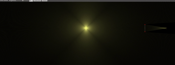
However, nothing is perfect in reality, which means we have to accept that the lens equation might not be perfectly satisfied for all the points in the subject, as that can only happen for an infinitesimally thin plane in the subject side. In the case the lens equation is not satisfied (i.e., as the dot moves in the subject side as shown in the animated gif), the image of the point source will look like a miniature image of the lens in the camera sensor plane. If the lens is a circle, then the image will look like a circle. This circle is the circle of confusion, i.e., the perfect point in the object side is “confused” by a circle in the image side.
The Aperture Effect
The presence of an aperture between the lens and the camera sensor change things a bit. The aperture cuts the light coming from the lens, effectively reducing the size of the circle of confusion. The animation below shows the circle of confusion being reduced in size when the aperture is closed. This allows the photographer to perform a trade off: If the circle of confusion is smaller, the image is acceptably sharp for a larger depth, increasing the depth of focus. But if the light is being cut off, then light is being lost and the image becomes darker, requiring more exposure or a more sensitive sensor. The markings on the side of the lens for different aperture openings (f/3.3, f/5, etc.) indicate the equivalent, or “effective” lens f-number used after the aperture was applied. Since the lens focal length cannot be changed, the equivalent lens is always smaller in diameter and therefore gathers less light. The shape of the “circle of confusion” usually also changes when using an aperture, as most irises are n-gons instead of circles. This effect is called “bokeh” and can be used in artistic photography.

Effect of the aperture on the circle of confusion.
Focusing on a Plane
Hopefully all of this makes more sense now. Now let’s make our example more complex and make two point sources, representing a line (or a plane) that we want to be in focus. We’ll start with the plane in focus, which means both points are at the same distance to the lens. Tilting the plane will make the circle of confusion of the plane edges grow (in the gif below, tilting the plane is represented by moving one of the points back and forth). This will result in a sharp edge on one side of the plane and a blurry edge on the other side.

The effect you get is usually seen in practice as the gradual blurring, as for example the image below shows. It becomes blurry because the circle of confusion is growing, but how much can it grow before we notice it? It depends how we define “noticing”. An “ultimate” reference size for the circle of confusion is the pixel size of the camera sensor. For example, the Nikon D5 (a mid-high level professional camera) has a pixel of around 6.45μm size. Cameras used in aerodynamics have pixels on that order (for example, a LaVision sCMOS camera has a 5.5μm pixel as of 2019). High speed cameras such as the Phantom v2012 will have much larger pixels (28μm) for enhanced light sensitivity. It makes sense to use the pixel size because that’s the sharpest the camera will detect. But in practice, unless you print in large format or you digitally zoom into the picture, it is very common to accept multiple pixels as the circle of confusion. With low-end commercial lenses, the effects of chromatic aberration far supersede the focus effect at the pixel level anyways. But bear in mind that if that is the case, your 35Mpx image might really be worth only 5Mpx or so. It is also generally undesirable to have only part of the image “Mathematically sharp” in a PIV experiment, since peak locking would happen only at a stripe of the image.

The Scheimpflug Principle
Well, this is the theory of sharpness, but how does the Scheimpflug principle help? Well, the next animation below attempts to show that. If you tilt the lens, the circles of confusion slowly grow to the same size, which means there would be a focal plane where they are the same exact size. I “cheated” a bit by changing the camera sensor size in the end, but in practice it is the camera that would be moving, not the object plane. This demo hopefully shows that there is a possible lens tilt angle that will bring everything in focus.

The Hinge Rule
Though I think much deeper explanations are available on the Internet (like on Wikipedia), I personally found that playing with the optical simulation makes more sense intuitively. Now we can try to understand what the Scheimpflug Hinge Rule is all about from a geometrical optics perspective.
The animation below defines two physical planes: The Lens Plane [LP], where the (thin) lens line lies; and the Sensor Plane [SP], where the camera sensor is placed. These planes, if the lens is tilted, will meet at a line (or a point, in the figure). This is the “hinge line”. The hinge line is important because it defines where the Focus Plane [FP] is guaranteed to go through. The hinge rule, however, would still be underdefined with only these planes.
The third reference line needed is defined by the Plane Parallel to Sensor at Lens Center [PSLC] and the Lens Front Focal Plane [LFFP]. The two lines are guaranteed to be parallel, and they define a plane – the Focus Plane [FP], where the point light sources are guaranteed to be in focus. A full proof of the Hinge Rule is readily available in Wikipedia and is not absolutely straightforward, so for our purposes it suffices to say that it works.

Lens Hinge vs Scheimpflug Hinge
Another confusing concept when setting up a Scheimpflug system is the fact that the Scheimpflug adaptor also usually possesses a hinge where it swivels about. That hinge line (the Lens Hinge) is not to be confused with the Scheimpflug Principle Hinge, explained before. But it does interfere when setting up a camera system because the Lens Hinge is the axis the lens is actually pivoting about, so it ends up changing the focal plane angle, where the camera is looking at, as well as the actual location of the focal plane. So I set up this little interactive Flash simulation here that determines the location of the plane of focus and allows you to understand the swivel movements I’m talking about. Here’s the link: http://www.fastswf.com/bHISKZA. There’s a little jitter for Scheimpflug angles close to zero due to “loss of significance” when performing the calculations, but it should be understandable.
Since most browsers aren’t very fond of letting Flash code run, you can also see a video of me focusing on an object plane (blue) below. In the animation, the camera/lens assembly swivels around the CH (Camera Hinge) axis and the lens swivels around the LH (Lens Hinge) axis. The Scheimflug Hinge (SH) is only used when performing the focusing movement of the camera. The focus optimization algorithm, however, is somewhat straightforward for a 2D (1 degree of freedom – 1 DOF) setup:
- Look at the object plane: Swivel the camera hinge CH until the camera looks at the object.
- Adjust lens focus: Turn the lens focus ring (effectively moving the lens back and forth) until at least some of the object is in focus.
- Change the Scheimpflug adaptor: Increase/decrease the Scheimpflug angle by some (arbitrary) value. This will make the camera look away from the object plane.
Repeat the three steps as much as you need and you should converge to a good focus as shown in the video. Sometimes I skip a step because it is unnecessary (i.e. the object is already partially in focus).
And here are the effects of the individual movements when using the Scheimpflug adaptor:
But Where’s the Lens Plane?
This one threw me off for a while, so I expect not everyone would be familiar with this. Let’s say you’re trying to design a Scheimpflug system and you are using regular camera lenses (i.e., a Nikon/Canon lens). These lenses contain multiple elements, so it is not straightforward what is the definition of “focal length” that the lens is rated for, and most importantly, where this “effective lens” lies in physical space.
This reference and many others provide formulas for finding the effective focal length (EFL) or multiple lens arrangements. If the link dies, here’s the equation for a two-lens arrangement:

The effective focal length depends on the two lenses focal distance (f1 and f2) as well as in the distance between the two lenses (d). But most importantly, you can swap f1 and f2 (say, if you flipped the lens arrangement) and the EFL will remain the same. This is usually the case in multiple lens arrangements, and this is why most DSLR lenses will be rated for a single focal length, which is their effective focal length.
The EFL can be regarded as a means to replace the complex lens arrangement with a single thin lens. But where is that “effective lens” in physical space? Well, that is a rather difficult question because most lenses will still have an adjustment ring for their focal distance. So, let’s start with a lens focusing at infinity.
Focusing at infinity is the same as assuming parallel rays are incoming to the lens. This means these parallel rays will form a sharp point exactly at the lens focal point (by definition). Well, if a compound lens is set to focus at infinity (most lenses will have an adjustment where you can focus at infinity) then that point must lie on the camera sensor. Therefore, this thin lens must be exactly its focal distance from the image sensor of the camera. If now we know the camera’s Flange Focal Distance (FFD), then we know exactly where this “Effective Lens” is sitting at with respect to the camera flange, as shown in the drawing below. For example, this FFD is 46.5mm in a Nikon camera. A comprehensive list for many cameras is found here. Also, as a bonus, the Phantom v2012 high speed camera has FFD=45.8mm when using the factory standard Nikon F-mount adaptor flange.

If now we change the focus ring of our 50mm lens to focus, say, at 500 mm distance. Then we can use the thin lens formula:

And find that for o=500 mm and f=50 mm we get i=55.5 mm. Therefore, the thin lens moved 5.5 mm away from the sensor to focus at 500 mm instead of infinity. If you look carefully, a lens will move farther from the sensor as we bring the focus closer:
Good. So this means that if we want to do some fancier photography techniques (like using the Scheimpflug principle), we can now use the EFL and its relationship to the FFD to calculate our Scheimpflug adaptor and the Scheimpflug angle needed to focus at a particular feature. Remember, in most practical setups the Scheimpflug adaptor will act as a spacer, thus preventing the lens from focusing at infinity. The more space added, the closer this “far limit” gets and the harder it becomes to work with subjects placed far from the camera.
Scheimpflug Principle in 3D [2-DOF]
So this was all under the 2D assumption, where we only need to tilt the lens in order to get the plane in focus. Easy enough for explanations, but you don’t really find that case very often in practice. If the object plane is tilted in the other direction (in 3D) we’ll need to compensate for that angle, too. That can be done by “swinging” the lens tilt axis. In a tilt-swing adaptor, there are two degrees of freedom for the lens angle. The “tilt” degree of freedom allows the lens to tilt as previously described. The “swing” degree of freedom swivels the lens around the camera, changing the orientation of the focal plane with respect to the camera. A little stop-motion animation, below, shows how these two angles change the orientation of the lens on the camera:
Or, if you’re a fan of David Ghetta, you might be more inclined to like the following animation (use headphones for this one):
When doing it in practice, however, it is rather difficult to deal with the two degrees of freedom. In my experience, the causes for confusion are:
- The object plane is static, and the camera is moving, but the movement is done with the lens first – this messes a little bit with the brain!
- When you tilt the lens, you need to move the camera back to see the subject because now the lens is pointing away from the object plane;
- It is rather hard to know if it is the tilt angle or the swing angle that needs adjustment in a fully 3D setup
- It is hard to know if you overshot the tilt angle when the swing angle is wrong, but it’s also difficult to pinpoint which one is wrong.
This compounds to endless and painful hours (yes, hours) of adjustment in an experimental apparatus – especially if you’re not sure of what exactly you’re looking for. Different than most professional photographers, it is usual in Particle Image Velocimetry to have rather shallow depth of field because we want to zoom a lot (like, using a telephoto 180mm lens to look at something 500mm from the camera) and we need very small f numbers to have enough light to see anything. Usual DoF’s are less than 5mm and the camera angle is usually very large (at least 30º). But enough of the rant. Let’s get to the solution:
First we need to realize that most Scheimpflug adaptors have orthogonal tilt / swing angle adjustments. In other words, the tilt and swing angles define a spherical coordinate system uniquely. This means there is only one solution to the Scheimpflug problem that will place the plane of focus in the desired location. With that said, it would be great if the solution for one of the angles (i.e., the swing angle) could be found independently of the other angle, because that would reduce the problem to the 2D problem described before.
The good news are that, in most setups, that can be done. To find the correct location of the swing angle:
- Get the normal vector of the target in-focus plane;
- Get the normal vector of the camera sensor;
- These two vectors form a plane. This is the “tilt plane”.
- We need the lens to tilt in this plane. To do so, the lens tilt axis needs to be normal to the “tilt plane”.
- Adjust the Scheimpflug swing such that the lens swivel axis is perpendicular to the “tilt plane”. That will be a “first guess” to the Scheimpflug swing. A solution is expected now, as you adjust the lens tilt. Or something very close to a solution, at least.
In practice there’s another complication related to the camera tripod swivel angle. If the axis the tripod is swiveling is not coincident with the axis of the “tilt plane”, then the problem is not 2D. That can be solved in most cases by aligning the camera again. But if that is not possible, usually it will require a few extra iterations on the “swing angle”, also.
Well, these definitions might be a little fuzzy in text. I prepared a little video where I go through this process in 2D [1-DOF] and 3D [2-DOF]. The video is available below.
Concluding Remarks
Well, I hope these notes help you better understand the Scheimpflug adaptor and be more effective when doing adjustments in your photography endeavors. In practice it is almost an “art” to adjust these adaptors, so I think an algorithmic procedure always helps speeding up things. Especially because these devices are mostly a tool for a greater purpose, so we are not really willing to spend too much time on them anyways.
Have fun!

what is the adaptor you’re using and whether it’s recommended? we use Nikkon F-mount lenses.
LikeLike
Hi, Alex, we use the scientific supplier LaVision in Europe. They provide Nikon C-mount to Nikon F-mount Scheimpflug adaptors for their cameras (i.e. the LaVision sCMOS, for example). It might be rather expensive for general use, though. A quick Amazon search shows a lot of adaptors (look for tilt-shift adaptor), which might also fulfill your needs.
LikeLike
Hi Fernando, i’m French Engineer. I work in an aerodynamics laboratory. I must do stereo PIV in wind tunnel. Usually, i use Photron fastcam SAZ with Lavision Scheimpflug but unfortunately one of two camera doesn’t work. I changed this cam by a Phantom v2640. But i have a problem with Scheimpflug, the distance between the sensor camera and the objective is too high and the distance of focusing at infinity is 20cm i need 100cm. How did you adapt the scheimpflug frames on your 2012?
Thanks
LikeLike
Hi, Damien, thanks for the contact. I understand your issue, I also have a similar issue with the Phandom v2012. On the v2012, I 3D printed an adaptor (see on Thingiverse the files: https://www.thingiverse.com/thing:3548501), it looks like it should also fit your camera – please check.
LaVision actually sells a shallow adaptor for the Scheimpflug to a Phantom camera, so you might contact them if you’re not comfortable with 3D printing.
LikeLike
Hi Fernando, I already asked Lavision for Scheimplug to my Phantom v2640 and and they don’t sell an adapter plate. May be that the distance between the sensor camera 2640 and the objective is higher than 2012… I try to put directly the Sheimpflug (lavision version 3 whitout adaptator plate) on the 2640 and the distance of focusing at infinity is 20cm. When i try with Lavision Sheimpflug version1 whitout adaptator plate the distance of focusing at infinity is 150cm but the angle max is 5° and i need to 20°… I believe that i will must do a new scheimpflug mount.
LikeLike
Yeah, Damien, this problem is quite frustrating. I also had this very same issue but I was able to just print that part and solve it. The 20º Scheimpflug adaptor acts as a spacer, that’s why you’re facing this issue. You can run the thin lens equation with the Scheimpflug spacer thickness added between the lens and the sensor, and play with the numbers; maybe you’ll find some combination that works.
I assume you’re using a lens with a long focal length, like 180mm or so, because that’s usually when it becomes an issue. Have you tried a lens with a shorter focal length? Usually the Scheimpflug “spacer” already increases magnification by a good amount (like 1.5 to 2); so you shouldn’t need a large focal length.
Also, make sure you really need 20º of Scheimpflug angle. That should give you a plane-to-camera angle of the order of 45 to 60º, which is not great for PIV.
If you must use that lens, there’s really no workaround I know; I’m afraid.
LikeLike